Welcome to a new series of articles that will be structured as lessons with the target of bringing SDN closer to everyone's understanding.
Each article will present a topic plus one or more exercises that will show that topic in action. The lessons will wrap up with some questions asking the readers to exercise on their own and provide the answers. As you see, the approach is pretty similar to the networking quizzes, but with SDN ones, I also make an introduction to the topic since all this is relatively new.
When I started my personal SDN journey, it was difficult to find a place to start, so I began reading articles, viewing presentations or listening to different videos, all trying to demonstrate (mostly theoretically) the advantages, the applications or limitations of this new technology.
I am a person who learns best by "doing", by individual testing, so I have decided to start these articles in order to help other network engineers with their beginnings in SDN.
In parallel, I will continue my series of network quizzes and solutions, hoping that time will allow me to do so...
Having started treating SDN topics clearly shows that I believe in this new approach in networking and after reading some introductory presentations and papers, one of the arguments that convinced me, was an analogy to the computer industry evolution from vertically integrated, closed, proprietary, relatively slow innovation, specialized-hardware, specialized-feature systems to horizontal, open interface, rapid innovation networking technology:

[1] Taken from Nick McKeown's presentation "How SDN will shape networking"
What is Software Defined Networking (SDN)?
SDN (Software Defined Networking) is a network architecture that breaks the vertical integration by separating the control logic (control plane) from the underlying routers and switches that will become simple forwarding elements (data plane). The four pillars to remember about SDN are: [2]
- the control and data planes are decoupled.
- forwarding decisions are flow-based instead of destination-based
- control logic is moved to an external entity, called SDN controller or NOS (Network Operatying System)
- network is programmable through applications running on top of the controller (the fundamental characteristic of SDN)
In order to put all the theory into practice, we will use Mininet, a virtual network environment that runs on a single machine and provides many of the OpenFlow features built-in. Mininet will emulate an entire network of switches, virtual hosts (running standard Linux software), the links between them and, optionally, a SDN controller (I will talk in details about the SDN controller and OpenFlow in future articles).
The switches generated with Mininet will be just simple forwarding devices, without any "brain" of their own (no control plane). The new networking paradigm with SDN is: control plane is separated from the data plane so such switches will only do what they are instructed by an external controller. Whenever a switch (or a forwarding device, generally speaking) does not know how to deal with some packets, it will simply send them to the controller (or contact the controller referrencing some buffer-ids - more on this later on).
Mininet supports research, development, learning, prototyping, testing, debugging, and any other tasks that could benefit from having a complete experimental network on a laptop or other PC.[3]
This may require a little bit of programming knowledge (Python), but you can also get it along the way...
Installing and Running Mininet
The installation of Mininet is pretty straight forward - in summary:
- 1. download the Mininet VM image,
- 2. open it with your favourite virtualization system (Virtual Box, VMware, VMFusion, Qemu or KVM)
- 3. then perform the walkthrough that will teach you how to use it (the entire walkthrough should take under an hour - no need to go though all of it now, just familiarize yourself with the basic commands).
The default run of Mininet sudo mn will create a topology consisting of one controller (c0), one switch (s1) and two hosts (h1 and h2).
To help you start up, here are the most important options for running Mininet:
--topo=TOPO represents the topology of the virtual network, where TOPO could be:minimal - this is the default topology with 1 switch and 2 hostssingle,X - a single switch with X hosts attached to itlinear,X - creates X switches connected in a linear/daisy-chain fashion, each switch with one host attachedtree,X - a tree topology with X fanout
--switch=SWITCH creates different type of switches, such as:ovsk - this is the default Open vSwitch that comes preinstalled in the VMuser - this is a switch running in software namespace (much slower)
--controller=CONTROLLER where CONTROLLER can be:ovsc - this creates the default OVS Controller that comes preinstalled in the VMnox - this creates the well-known NOX controllerremote - does not create a controller but instead listens for connections from external controllers
--mac set easy-to-read MAC addresses for the devices
For our exercise, we will create a virtual network with one switch and 3 hosts, using the command shown below:

For the moment, we will not touch the topic of SDN controller so our test network will have no controller. For such a switch to be able to forward traffic, it needs to be told how to handle the flows (again a topic for future articles).
In order to "control" the switch (to add and view the status of the flows on the switch) we will use an utility called DPCTL that allows direct control and visibility over switch's flow table without the need to add debugging code to the controller. Most OpenFlow switches have a passive listening port running on TCP 6634 (by default) that can be used to poll flows and counters or to manually insert flow entries.
You can use this utility directly under the mininet prompt or in a separate console by connecting to the listening port as indicated below:
dpctl COMMAND tcp:127.0.0.1:6634 OPTIONS
where COMMAND can be:
- show
- dump-flows
- add-flow
In our first exercise, let's configure our virtual network in order to make host h1 successfully ping host h2. Follow these steps:
STEP 1: Start Mininet with a single switch (the default, Open vSwitch = ovsk) and 3 hosts:
mininet@mininet-vm:~$sudo mn --topo=single,3 --mac --switch=ovsk --controller=remote *** Creating network *** Adding controllerUnable to contact the remote controller at 127.0.0.1:6633 *** Adding hosts: h1 h2 h3 *** Adding switches: s1 *** Adding links: (h1, s1) (h2, s1) (h3, s1) *** Configuring hosts h1 h2 h3 *** Starting controller *** Starting 1 switches s1 *** Starting CLI: mininet> mininet>nodes available nodes are: c0 h1 h2 h3 s1 mininet> mininet> mininet>net h1 h1-eth0:s1-eth1 h2 h2-eth0:s1-eth2 h3 h3-eth0:s1-eth3 s1 lo: s1-eth1:h1-eth0 s1-eth2:h2-eth0 s1-eth3:h3-eth0 c0 mininet> mininet>dump <Host h1: h1-eth0:10.0.0.1 pid=9730> <Host h2: h2-eth0:10.0.0.2 pid=9731> <Host h3: h3-eth0:10.0.0.3 pid=9732> <OVSSwitch s1: lo:127.0.0.1,s1-eth1:None,s1-eth2:None,s1-eth3:None pid=9735> <RemoteController c0: 127.0.0.1:6633 pid=9723> mininet>
As you can see, we receive this message: "Unable to contact the remote controller at 127.0.0.1:6633". This is because, for the time being, we are going to use mininet without any controller (cli argument --controller=remote tells mininet that we are going to use an external controller, but for this lesson, we don't need it).
In order to double-check that everything started correctly, use the following mininet commands:
- nodes - to list all virtual devices in the topology
- net - to list of links between them
- dump - to see more info about the hosts
STEP 2: Open terminals for each host and run tcpdump on each:
Attention: for Windows users, make sure you installed & run Xming, plus you enabled X-forwarding in your ssh session to the Mininet VM!
STEP 3: Test connectivity between h1 and h2: on host h1 perform a ping -c3 10.0.0.2 (the IP address of host h2)
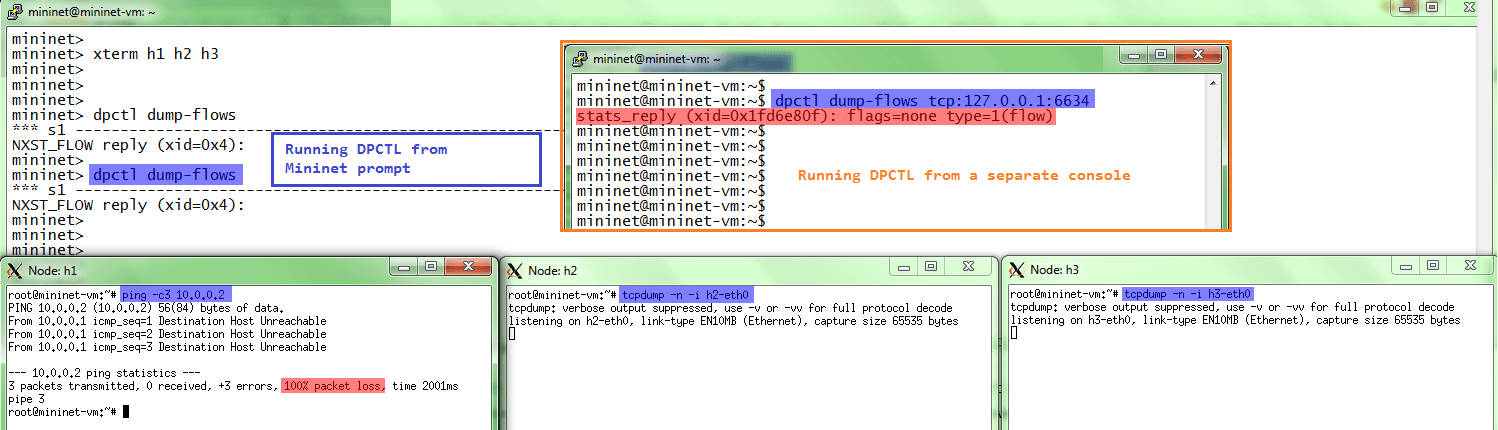
Results:
ping will fail , because the switch does NOT know what to do with such traffic (and remember, we don't run any controller)- checking the list of flows on the switch (with command
dpctl dump-flows) will show an empty list (again, nobody told the switch how to deal with the traffic)
STEP 4: Manually add flows on the switch to allow connectivity between h1 and h2
Use the dpctl add-flow utility to manually install flows on the switch that will allow connectivity between host h1 and host h2.
Attention: we need two rules to achieve a bidirectional connectivity (echo request and echo replies):
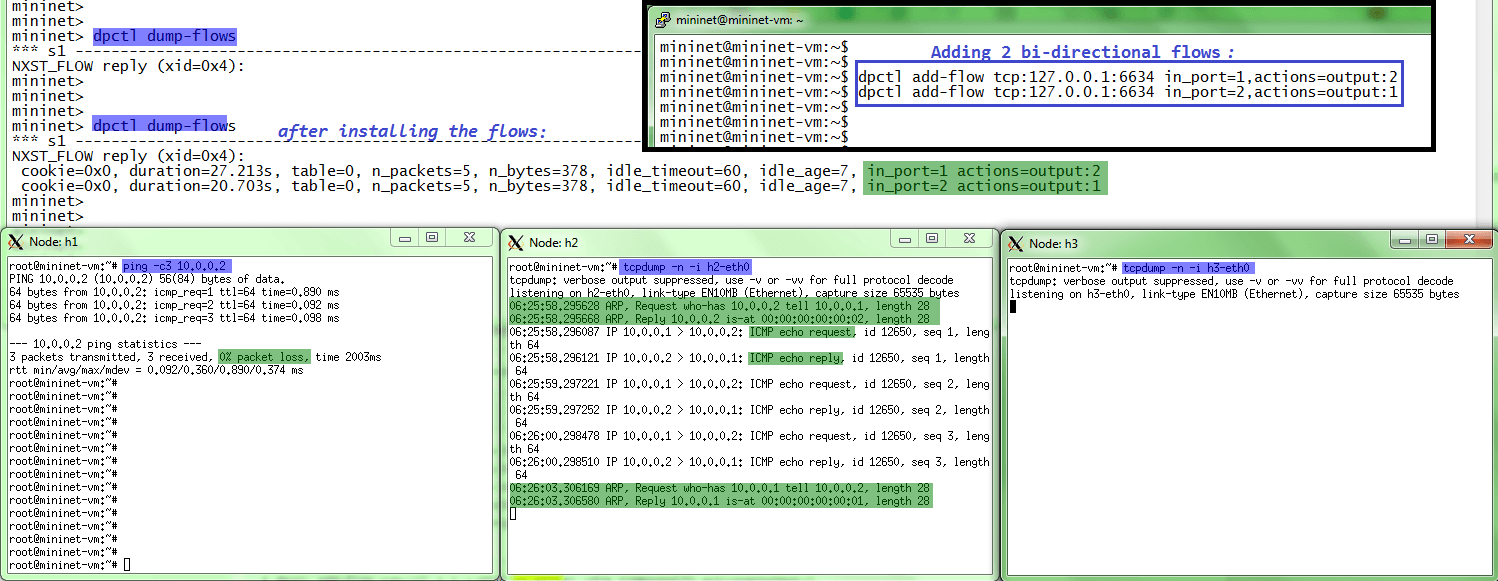
The 2 commands basically say:
dpctl add-flow tcp:127.0.0.1:6634 in_port=1,actions=output:2= everything received on port 1 (in_port) send out on port 2dpctl add-flow tcp:127.0.0.1:6634 in_port=2,actions=output:1= everything received on port 2 (return traffic) send out on port 1
Result:
- ping is
successful - tcpdump on host h2 shows the traffic from/to h1 (ARP and ICMP)
- tcpdump on host h3 does
not see anything (not even the ARP which should be broadcast )!
SDN Exercise #1
The first exercise in the SDN series will use the above setup, but with the additional requirement of treating ARP traffic as broadcast:
- ARP requests (no matter input port) are flooded on all switch ports
- ICMP traffic between hosts h1 and h2 is unicasted on the relevant ports
What are the relevant
Post your answer in the 'Comments' section below and subscribe to this blog to get more interesting SDN lessons and quizzes.
After completing this exercise, you should be able to see this:

- ARP request from host h1 are received by both h2 and h3 (highlighted in green)
- ICMP echo requests from host h1 to h2 are only seen by h2 (highlighted in yellow)
References
- [1] Nick McKeown's presentation "How SDN will shape networking"
- [2] Software-Defined Networking: A Comprehensive Survey
- [3] Mininet Overview
- [4] dpctl command reference
Thanks again for all your comments !
 Costi is a network and security engineer with over 10 years of experience in multi-vendor environments. He holds a CCIE Routing and Switching certification and is currently pursuing same expert-level certifications in other areas. He believes that the best way to learn and understand networking topics is to challenge yourself to fix different problems, production-wise or lab-type exams. He also enjoys teaching networking and security technologies, whevever there is an opportunity for it.
Comments
comments powered by Disqus