This is the solution for quiz-13 that covers Frame Relay, a topic that is very hard to find it implemented in today's networks but often seen during certification exams, as it still part of the curriculum for some of them.
In the real world, Frame Relay was mostly replaced by MPLS but there could still be companies that have Frame Relay, probably due to the long-time contracts signed with their providers. Anyway, even in these cases, it’s almost certain that you will not find an end-to-end Frame Relay connection these days, but rather FR on the last mile and MPLS in the provider’s core.
One of the challenge with Frame Relay networks is represented by the difference between the layer 2 connectivity and layer 3 view (what layer 3 protocols “think” about layer 2), again due to the fact that in the absence of broadcast, it could be very difficult to discover all the devices connected at layer 2 - this is mostly common in partial-mesh or hub-and-spoke topologies.
For example, all devices connected to the same Ethernet broadcast domain are able to see each other (using broadcast or multicast) but in case of Frame Relay more devices could be connected to the same link but they don't necessary have direct connectivity between each other (spoke-to-spoke communication occurs via the hub when there is no virtual circuit between them).
In order to find the layer 3 address of other DTE neighbors, Frame Relay routers uses dynamic mapping, via Inverse ARP, or static entries.
Address Resolution via Dynamic Mapping: Inverse ARP
Each DTE router learns the DLCI via the LMI messages but it does not know what is the IP address of the neighboring device or devices. The process of discovering the IP address of the remote end is called Inverse ARP (InARP), thus creating mapping between local DLCI and the remote end's protocol address.
The name “Inverse ARP” comes from the fact that “normal” ARP is used to discover the layer-2 MAC address having the layer-3 IP address, while in case of Frame Relay, the DLCI (layer-2 address) is already learnt via LMI but it does not know the layer-3 address (so it is an “inverse” logic).
Once an IP address is configured on an interface connected to the Frame Relay cloud, InARP messages containing that IP address are sent on all DLCI on that interface.

In the diagram, R1 sends InARP requests with its IP 192.168.1.1 on both DLCI 102 (towards R2) and DLCI 103 (towards R3) and, based on the received InARP replies, it will map IP 192.168.1.2 to DLCI 102 and IP 192.168.1.3 to DLCI 103.
There are several important notes that need to be remembered:
- Inverse ARP cannot work without
LMI[...see Roman's comment below...] both DLCI & IP address, because LMI is the mechanism used to learn about the DLCI associated with that interface (without LMI the router does not learn any DLCI, so it cannot send InARP messages) [...added: if you disable LMI but you manually configure a DLCI on that interface then InARP will work...] - all DLCIs learned via LMI are automatically associated with the main interface, so the Inverse ARP requests are generated only by the main interface
- by default, Inverse ARP supports broadcasts - notice the broadcast word in the output of "show frame-relay map"
- Inverse ARP is automatically enabled by LMI (unless disabled by static mapping as we will see below)
Address Resolution via Static Mapping
Inverse ARP is a dynamic mechanism of mapping IP address to a DLCI, but the same result can be achieved with static mapping via manual configuration.
A very important note here (and easily overlooked during exams) is that the static mapping disables the Inverse ARP for the pair (protocol, DLCI) - where the protocol is IP. This is actually the key to the quiz.
Suppose that you create static mapping for IP 192.168.1.2 to DLCI 102 – then, this will automatically disable InARP for the pair (IP, DLCI 102).
Actually, the static mapping does not disable InARP completely - only the InARP requests - but the router will still reply to the InARP messages, if it receives any!
For full explanation about Frame Relay technology, please read Demystifying Frame Relay article.
Quiz Review
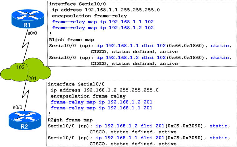
The two routers in the quiz (R1 and R2) are using initially dynamic mappings (via Inverse ARP) to learn about each other:

Later on, when the network engineer adds the static mapping for its own IP address, everything looks ok, at least for a while:
R1# interface Serial0/0 ip address 192.168.1.1 255.255.255.0 encapsulation frame-relayframe-relay map ip 192.168.1.1 102 endR1#sh frame map Serial0/0 (up): ip 192.168.1.1 dlci 102(0x66,0x1860), static, CISCO, status defined, active Serial0/0 (up): ip 192.168.1.2 dlci 102(0x66,0x1860), dynamic, broadcast,, status defined, active R1# R1#ping 192.168.1.1 Type escape sequence to abort. Sending 5, 100-byte ICMP Echos to 192.168.1.1, timeout is 2 seconds:!!!!! Success rate is 100 percent (5/5), round-trip min/avg/max = 4/40/116 ms R1# R1#ping 192.168.1.2 Type escape sequence to abort. Sending 5, 100-byte ICMP Echos to 192.168.1.2, timeout is 2 seconds:!!!!!** Success rate is 100 percent (5/5), round-trip min/avg/max = 4/39/84 ms R1#
R2# interface Serial0/0 ip address 192.168.1.2 255.255.255.0 encapsulation frame-relayframe-relay map ip 192.168.1.2 201 endR2#sh frame map Serial0/0 (up): ip 192.168.1.2 dlci 201(0xC9,0x3090), static, CISCO, status defined, active Serial0/0 (up): ip 192.168.1.1 dlci 201(0xC9,0x3090), dynamic, broadcast,, status defined, active R2# R2#ping 192.168.1.1 Type escape sequence to abort. Sending 5, 100-byte ICMP Echos to 192.168.1.1, timeout is 2 seconds:!!!!! Success rate is 100 percent (5/5), round-trip min/avg/max = 4/38/80 ms R2# R2#ping 192.168.1.2 Type escape sequence to abort. Sending 5, 100-byte ICMP Echos to 192.168.1.2, timeout is 2 seconds:!!!!! Success rate is 100 percent (5/5), round-trip min/avg/max = 4/36/148 ms R2#
The problem is that this apparently working status will last only as long as the dynamic entry exists.
If for any reason (interface reset, clearing of dynamic mappings, device reboot) the dynamic entry disappears, it will never re-appear because of the additional static mapping configured in the meantime.
As explained in the above section "Address Resolution via Static Mapping", the static mapping disables the Inverse ARP for the pair (protocol, DLCI) - in our case, Inverse ARP will be disabled for pair DLCI 102 - protocol IP.
So, you cannot use both dynamic and static mapping for the same DLCI/protocol pair!
Quiz Solutions
Considering the requirement of the quiz (make the routers be able to ping their own IP addresses), I suggest the following solutions:
1. Create static entries for both IP addresses (itself and peer)
In this case we will avoid having both dynamic and static mappings for same protocol/DLCI pair, situation that appeared due to a race condition (the dynamic entry was created before the static one):
2. Create point-to-point sub-interfaces
This also represents a solution because point-to-point sub-interfaces do not "need" mappings, routers just sent any data onto the sub-interface:

Note that this solution may not be suitable/available in all scenarios.
Thank you for your comments and interest in the quiz!
 Costi is a network and security engineer with over 10 years of experience in multi-vendor environments. He holds a CCIE Routing and Switching certification and is currently pursuing same expert-level certifications in other areas. He believes that the best way to learn and understand networking topics is to challenge yourself to fix different problems, production-wise or lab-type exams. He also enjoys teaching networking and security technologies, whevever there is an opportunity for it.
Comments
comments powered by Disqus